From Dev Board to Volume: Taking a Micro OLED Design Into Production
A working prototype proves that the design can function once. Production asks whether it can function a thousand times with components from different batches, assembled by people who did not design it, and tested by a procedure that somebody else wrote. For a display assembly that transition surfaces questions about panel tolerance, connector and flex variation, firmware configuration and acceptance testing. None of them are exotic, and all of them are cheaper to answer before tooling than after. The sections below are the ones that most often get deferred and then cause the most trouble.
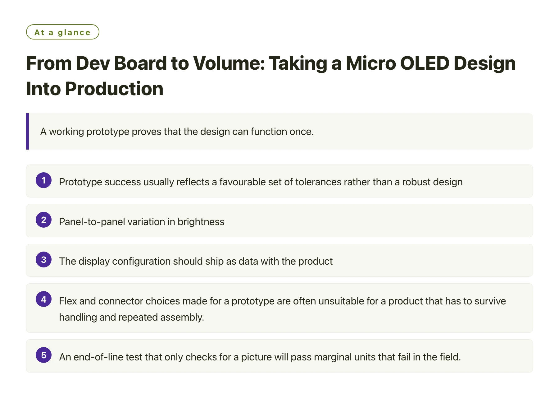
Key takeawaysPrototype success usually reflects a favourable set of tolerances rather than a robust design, so the first task is to find out which tolerances matter. · Panel-to-panel variation in brightness, colour and timing has to be characterised before an acceptance limit can be written. · The display configuration should ship as data with the product, so a panel revision does not require a firmware release. · Flex and connector choices made for a prototype are often unsuitable for a product that has to survive handling and repeated assembly. · An end-of-line test that only checks for a picture will pass marginal units that fail in the field.
The transition to production is not a single gate but a series of small decisions, most of which are about variability. The prototype exists at one point in a space of tolerances; production has to work across that whole space.
Display assemblies add two specific complications. First, the panel is a purchased component with its own manufacturing spread, which the assembler does not control. Second, the visual result is judged by people, so the acceptance criteria have to be written rather than assumed.
There is also a documentation dimension. When somebody else builds the product, they need to know not only what to assemble but what to verify and what to do when a unit fails. A display design that cannot answer those questions is not ready for volume, however well it performs on the bench.
Find the tolerances that actually matter
The useful exercise after a working prototype is to ask which measurements would have to change for it to stop working. Rail voltage, clock frequency, cable length, ambient temperature, panel batch, connector seating. Each one has a range over which the design functions, and the prototype sat somewhere inside it.
Production then has to live within the intersection of all those ranges. Where the intersection is wide, the design is robust and no further work is needed. Where it is narrow, that specific tolerance has to be tightened, tested or designed out.
Displays make this exercise practical because most of their variation is observable. Brightness and colour spread can be measured, timing variation can be captured on a scope, and mechanical tolerance around the connector can be checked with a gauge. The measurements are straightforward; the discipline is writing them down and repeating them across several units. That is also the point at which a supplier's published data for parts such as DisplayModule display modules stops being background reading and becomes part of the production record.
What changes between prototype and volume
| Area | What the prototype tolerated | What production demands |
|---|---|---|
| Panel variation | One unit, hand-selected and characterised on the bench | Sampled measurement across batches and an acceptance limit derived from the data |
| Cable and connector | A short flex chosen for convenience during layout | A defined part with controlled impedance, a specified bend radius and a repeatable assembly method |
| Firmware configuration | Values tuned on the bench and left in the source | A versioned configuration that identifies the panel revision it applies to |
| Assembly process | Engineer discretion about seating and alignment | Written instructions and a fixture that makes correct assembly the easy option |
| End-of-line test | Visual inspection of a picture | A defined pattern set with measurable pass criteria and a record for each unit |
| Change control | Informal, because the design was still moving | A documented route for panel, firmware and mechanical changes |
Three questions that are usually deferred too long
Each of these looks like paperwork until a batch of units is affected, at which point it becomes an engineering emergency.
Who owns the display configuration
On the bench, the person who wrote the driver owns it. In production, the panel design, the configuration values and the firmware version have to be traceable to each other, so that a unit in the field can be identified and a change can be scoped.
The simplest arrangement that works is a versioned configuration file that names the panel revision it targets, checked into the same repository as the firmware, with a serial number record linking units to the version they shipped with.
How marginal units are caught
A test that displays a picture confirms that the display works. It does not catch a unit with slightly low luminance, a marginal interface margin or a connector that will fail after a hundred thermal cycles. Those units pass and then generate returns.
Better end-of-line tests are not necessarily complex. A defined set of patterns at a fixed drive level, measured with a simple fixture, catches most marginal cases. Where a measurement is impractical, a functional stress, such as running the interface at the edge of its specified range for a short period, is a useful substitute [1].
Whether the product is compliant where it ships
Material and recycling obligations differ by market, and display assemblies are affected by them [2]. The compliance file needs declarations from the panel supplier, and those declarations need to be refreshed when a module changes. This is the classic example of a task that is cheap to keep current and expensive to reconstruct.
A production readiness pass for a display assembly
- Measure five units, not oneCharacterise luminance, colour and interface margin across several panels from at least two batches before writing any acceptance limit.
- Freeze the mechanical interfaceLock the connector part, the flex length and the bend radius, and build a gauge that confirms correct assembly in one step.
- Version the display configurationTie the register values to a panel revision and record which version each unit shipped with.
- Write the end-of-line test with limitsSpecify patterns, drive levels, measurement method and pass thresholds. An inspector should never have to exercise judgement about whether an image looks acceptable.
- Decide how a panel change is handledAgree what counts as an equivalent replacement and what triggers a re-qualification, before a supplier is in a position to make that decision for you.
- Re-test after the first real batchCompare measurements from the first production batch against the prototype baseline. The differences are the most informative data the project will produce.
The most expensive phrase in a production project is "it worked on the prototype". Treat the prototype as one sample of a distribution, find the width of that distribution for every parameter that matters, and write the acceptance criteria from the data. That is the whole difference between a design that works and a product that ships.
Sources
Frequently asked questions
How many units should be characterised before setting display acceptance limits?
Enough to see the spread, and ideally from more than one batch. Five units across two batches is a reasonable minimum for a small display module, and the resulting limits should be re-checked against the first real production batch before they are treated as final.
Should display configuration live in firmware or in a data file?
In a data file, versioned alongside the firmware and naming the panel revision it applies to. That makes a panel change a review of one file, gives you a record of which units shipped with which configuration, and keeps bench workarounds visible instead of buried in driver code.
What should an end-of-line test check on a display assembly?
At minimum, a defined pattern set displayed at a fixed drive level, with measurable criteria for luminance, uniformity and correct colour order, plus a check that the interface works at the edges of its specified range. Visual inspection alone passes marginal units that later fail in the field.
How should a panel change be handled mid-production?
Through an agreed definition of form, fit and function, with a notification period and a re-qualification path. If the replacement changes timing, thickness or interface mode, treat it as a design change and re-run the relevant tests rather than accepting it as a drop-in substitute.